How to create a hierarchical IPv6 addressing plan
This document describes how to design a hierarchical IPv6 addressing plan on the basis of an example of a multinational organization with the help of the free online Hierarchical Addressing Plan Builder.In our example we create the first subnet levels of the address allocation scheme from the organizations Locations and the last subnet level from the Use Type of the networks. You can use the Hierarchical Addressing Plan Builder to create other types of allocation schemes like pure Location based or pure Use Type (functional) based, too.
Some goals of such a mixed approach are:
- Address allocation scheme reflects the organization's infrastructure
- It's possible to recognize directly from the IPv6 address to what location/environment a network belongs to
- It improves routing aggregation and reduce the load on the routers because it provides contiguous address spaces for each location
- It takes organization's future growing in mind
The organization consist in one campus in New York, two campi in Berlin and 10 offices in different cities in North-America, Europe and Asia.
A hierarchical structure for the organization could consist in:
- Level I: Continents
- Level II: Lands
- Level III: Cities
- Level IV: Campi
- Level V: Buildings
- Level VI: Network environments (production, pre-production, development, test, human-recurses, marketing, corporate, ....)
- Level VII: End networks with hosts (prefix length /64)
When we associate the organizations topology with the different levels we get the following table:
| Level I (Contient) | Level II (Land) | Level III (City) | Level IV (Campus) | Level V (Building) | Level VI (Network environment) |
| North America | USA | NY | Campus NY | Building 1 | production |
| pre-production | |||||
| development | |||||
| corporate | |||||
| ... | |||||
| Building 2 | production | ||||
| pre-production | |||||
| development | |||||
| corporate | |||||
| ... | |||||
| Washington | Office Wash (no campus) | Office Wash | production | ||
| pre-production | |||||
| development | |||||
| corporate | |||||
| ... | |||||
| Canada | Toronto | Office Toro (no campus) | Office Toro | production | |
| pre-production | |||||
| development | |||||
| corporate | |||||
| ... | |||||
| Europe | Germany | Berlin | Campus I Berlin | Building 1 | production |
| pre-production | |||||
| development | |||||
| corporate | |||||
| ... | |||||
| Building 2 | ... | ||||
| Building 3 | ... | ||||
| Building 4 | ... | ||||
| Building 5 | ... | ||||
| Campus II Berlin | Building 1 | ... | |||
| Building 2 | ... | ||||
| Hamburg | Office 1 Ham (no campus) | Office 1 Ham | ... | ||
| Office 2 Ham (no campus) | Office 2 Ham | ... | |||
| Munich | Office Mun (no campus) | Office Mun | ... | ||
| England | London | Office Lon (no campus) | Office Lon | ... | |
| Spain | ... | ||||
| France | ... | ||||
| Asia | Japan | ... | |||
| India | ... | ||||
| ... |
Now lets build the addressing plan.
In the first step we need to define what prefix length (how many networks) we want to use for every network level. In the second step we assign the organization's Locations to the different network levels and create the addressing plan. The addressing plan can be exported to CSV-format (coma separated value) which can easily be imported into a spreadsheet application or an IP address management (IPAM) system like GestióIP.
The ISP assigned the IPv6 network 2001:DB8::/32 to the organization.
With the infrastructure above we need at least:
- 3 level I networks (North-America, Europe, Asia)
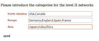
- 4 level II networks (maximal 4 countries per continent) Europe: Germany, England, Spain, France
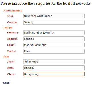
- 3 level III networks (maximal 3 cities per country) Germany: Berlin,Hamburg,Munich
- 2 level IV networks (maximal 2 campi per city) Berlin: Campus 1, Campus 2
- 5 level V networks (maximal 5 buildings per campus) Campus Berlin 1: Building 1-5
- 10 level VI networks (maximal 10 network environments per building) same for all buildings: production, pre-production, development, test, human-recurses, marketing, corporate, ....
- 351 level VII networks (the organization has maximal 351 networks (/64) per network environment. E.g. 351 production networks in building 1 of campus 2 in Berlin (the datacenter of the organization))
Access to the Hierarchical Addressing Plan Builder and calculate the from your ISP assigned address 2001:DB8::/32
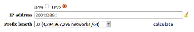
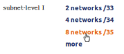
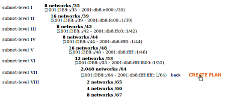
The tool displays a list of possible level I networks.

The first number (2) is the number of possible networks, the second number (/33) the prefix length of the networks for this level.
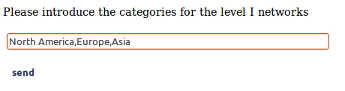
We need at least 3 level I networks to map the actual topology (three continents: North America,Europe,Asia).
Now we have to take future growing in mind. Actually the organization has buildings on three continents. So we need at least three level I networks. As a prefix length of /33 only offers two level I networks we need to choose at least a prefix length of /34, which offers four level I networks. But the organization may open in the future offices in Sydney (Australia) and Buenos Aires (South-America), so a prefix length of /34 would not offer sufficient networks for the future structure. Because of this we choose a prefix length of /35 with offers up to eight level I networks.
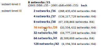
We need at least 4 level II networks for the lands per continents. As a prefix length of /37 allows exact 4 level II networks and therefor does not offer free networks for future growing, we choose a prefix length of /39 with allows 16 subnets
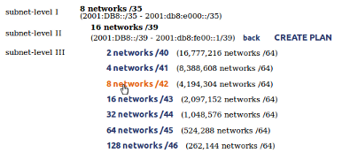
We need at least 3 level III networks for the cities per land. A prefix length of /41 allows only up to 4 level III networks (cities) per land. We choose here a prefix length of /42 (8 networks) to take futur growing in mind.
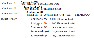
We need at least 2 level IV networks for the campi per city. We choose a prefix length with offers us 4 networks for campi per city.
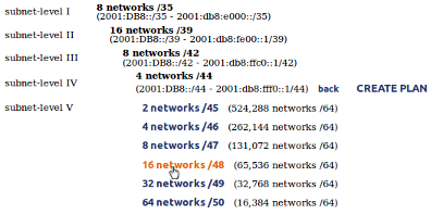
We need at least 5 level V networks for the buildings per campus.
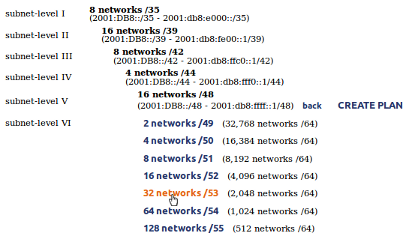
We need at least 10 level VI networks for the different network environments per building.
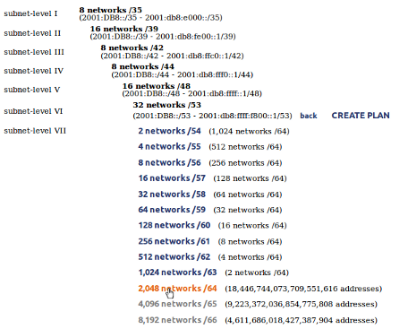
We need at least 351 level VII networks per network environment. The networks of the last level (networks which contains hosts) should always have a prefix length of /64.
Click "CREATE PLAN" to access to the Hierarchical Addressing Plan Builder.
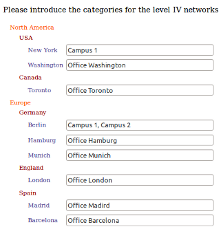
In the second step we map organization's topology to the different network levels and create the addressing plan.
Level I: continents
Level II: lands
Level III: cities
Level IV: campi
If there is just a single office and no campus in the city we use the office as level IV and as level V category.
Level V: buildings
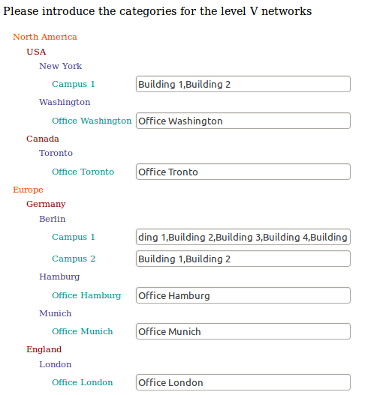
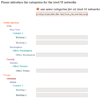
Level VI: network environments
It's recommended to use the same network environments for every building independently if the network environment exists in the building or not. That permits a standarized nummeration of the networks and gives us the possibility to recognize the network environment directly from the IP address.
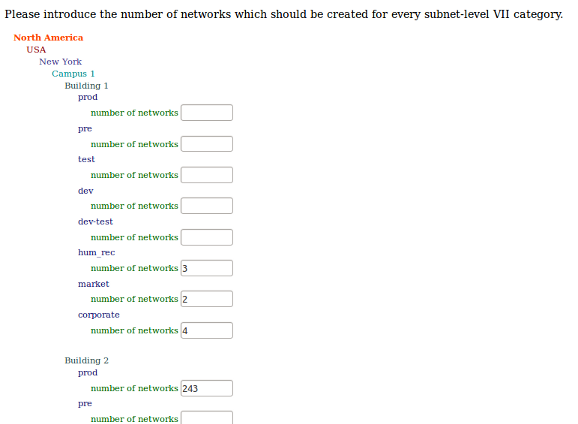
Level VII: networks per network environment
Introduce the number of networks (/64) which should be created for every network environment. Leave the "number of networks" fields blank for the network environments which do not exists within a building. In our example building 1 of campus 1 in New York contains parts of the marketing and human recurse department and no production or preproduction networks.
After you have determined how many networks should be created for every network level press "send" at the bottom of the page to create the addressing plan.
The addressing plan will be presented in form of a list.
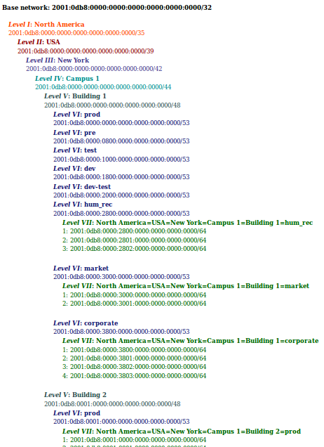
Note: only the first 20 /64 (last level) networks will be displayed in this view. Use the "export" button at the end of the page to export the entire IPv6 addressing plan.
And how can I recognize to which continent, city or network environment a network belongs to?
In our example the significant bits for the continents (level I, prefix length /35) are the first three bits of the third address octet: 2001:0db8:0000:0000:0000:0000:0000:0000 (see Table 2)
Networks in North America always have this bits set to 0: 2001:0db8:0000:0000:0000:0000:0000
Networks in Europe always have this bits set to 2: 2001:0db8:2000:0000:0000:0000:0000
The significant bits for the network environment (level VI, prefix length /53) are the five first bits of the fourth address octet: 2001:0db8:0000:0800:0000:0000:0000:0000
Production networks always have this bits set to 00: 2001:0db8:0000:0000:0000:0000:0000:0000 (independently if the are in New York, Berlin or Hong Kong)
Pre-production networks always have this bits set to 08: 2001:0db8:0000:0800:0000:0000:0000:0000 and
Marketing networks always have this bits set to 30: 2001:0db8:0000:3000:0000:0000:0000:0000
So if we see the address 2001:0db8:20a6:08e3:0000:0000:0000:0000 we know that this is a pre-production network in Europe.
Table 2 shows the distribution of the significant bits for all levels:
| Level | Prefix length | hexadecimal address | third and fourth octet in binary (P=2001:0db8) |
| I | 35 | 2001:0db8:0000:0000:: | P:0000 0000 0000 0000:0000 0000 0000 0000:: |
| II | 39 | 2001:0db8:0000:0000:: | P:0000 0000 0000 0000:0000 0000 0000 0000:: |
| III | 42 | 2001:0db8:0000:0000:: | P:0000 0000 0000 0000:0000 0000 0000 0000:: |
| IV | 44 | 2001:0db8:0000:0000:: | P:0000 0000 0000 0000:0000 0000 0000 0000:: |
| V | 48 | 2001:0db8:0000:0000:: | P:0000 0000 0000 0000:0000 0000 0000 0000:: |
| VI | 53 | 2001:0db8:0000:0000:: | P:0000 0000 0000 0000:0000 0000 0000 0000:: |
| VII | 64 | 2001:0db8:0000:0000:: | P:0000 0000 0000 0000:0000 0000 0000 0000:: |
Nibble boundaries
As you see in the table, some four-bits-blocks of our example allocation scheme are significant for more than one level (assignments made on non-nibble boundaries). If you need that your address allocation scheme respects the nibble boundaries, assign only the following prefix lengths: ...28, 32, 36, 40, 44, 48, 52, 56, 60, 64 (prefix length divisible by 4). That would make sure that the significat bits always appear in blocks of four bits (a prefix length of e.g. /32 means, that you use the first 32 bits of the IPv6 address for the prefix part).
| Level | Prefix length | hexadecimal address | third and fourth octet in binary (P=2001:0db8) |
| I | 36 | 2001:0db8:0000:0000:: | P:0000 0000 0000 0000:0000 0000 0000 0000:: |
| II | 40 | 2001:0db8:0000:0000:: | P:0000 0000 0000 0000:0000 0000 0000 0000:: |
| III | 52 | 2001:0db8:0000:0000:: | P:0000 0000 0000 0000:0000 0000 0000 0000:: |
| IV | 64 | 2001:0db8:0000:0000:: | P:0000 0000 0000 0000:0000 0000 0000 0000:: |
Exporting the addressing plan
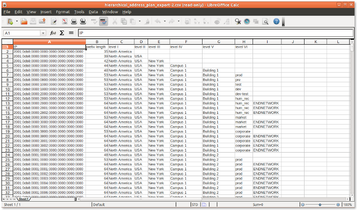
It's possible to export the IPv6 addressing plan to CSV format which can be imported with a spreadsheet application (e.g. Libre Office Calc, MS Excel). Click "export" to export the addressing plan. Open it directly with a spreadsheet application or save it to your disk. Choose "Comma" as separator and UTF-8 as character set when importing the CSV file.
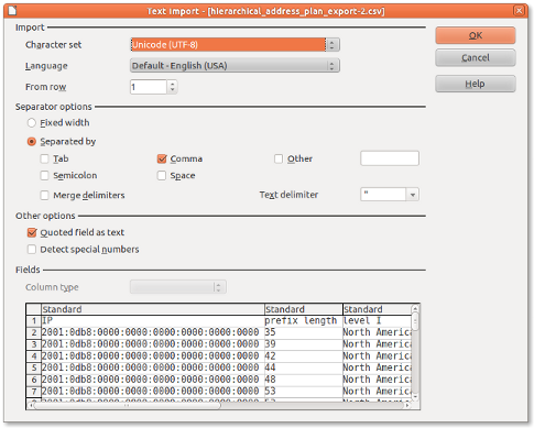
Note: CSV data will be dynamically created and directly be streamed. No data will be saved on the server.
Questions, comments, bugs: mailto contact@gestioip.net